Setting Up Multiple GigE Cameras with Spinnaker
Applicable Products
All Teledyne FLIR Machine Vision GigE cameras, including GigE, 5GigE, and 10GigE models.
Overview
When choosing to do a multi-camera system setup, there a number of parameters necessary to reivew to ensure a successful setup. Specifically:
- Using multiple GigE host adapters or a switch will determine the overall bandwidth limitation seen by a camera. Using multiple host adapters means each host adapter provides full interface bandwidth; using hubs/switches may limit total camera bandwidth to the interface bandwidth limit, but they can also be used universally by desktop, laptop and embedded system devices.
- DeviceLinkThroughputLimit is a camera setting that determines the total bandwidth each camera can take up. When using multiple cameras on one bus/host adapter, it is important to reduce this to ensure that the combined bandwidth of all of the cameras do not exceed the bandwidth limitations of the interface, while maintaining a certain value to achieve your application required resolution/framerate combination.
- System Components are important to determine the processing performance of a computer/host system. It's important to know the specifications necessary to run multiple cameras, and what kind of performance you can expect for a given hardware system.
This article provides details on system setups we have tested using multiple cameras, the camera settings used to achieve that bandwidth, and things to look out for when configuring your own multi-camera system.
Recommended Hardware Systems
When choosing a system, prioritize in getting a CPU with Turbo Boost and dual channel DDR4 or DDR5 RAM at least 2666 Mhz.
The following table has three systems that were tested with multiple Blackfly S GigE, Oryx 10GigE, and Forge 5GigE cameras.
|
COMPONENT |
DESCRIPTION for Oryx or Blackfly S |
DESCRIPTION for Forge |
|
|
Camera |
1 x ORX-10G-123S6C 1 x ORX-10G-123S6M OR 3 x BFS-PGE-50S5C 2 x BFS-PGE-13Y3C 2 x BFS-PGE-23S3C 1 x BFS-PGE-16S2C |
1 x FG-P5G-50S4C 1 x FG-P5G-50S4C 2 x FG-P5G-50S4M |
1 x FG-P5G-50S4M 1 x FG-P5G-50S4M 2 x FG-P5G-50S4C |
|
Motherboard |
AIMB-786G2-00A1 |
OptiPlex 5000 Tower |
ASUS PRIME Z690-P D4 |
|
Chipset |
96MPI7C-3.2-12M11T Intel® Core™ i7-8700 CPU @3.20 GHz |
12th Gen Intel® Core™ i7-12700 (25 MB cache, 12 cores, 20 threads, 2.10 GHz to 4.90 GHz Turbo, 65 W) |
12th Gen Intel® Core™ i3-12100 @3.30 GHz 12th Gen Intel® Core™ i5-12400 @2.50 GHz |
|
Memory |
2 x 8 GB DDR4-2666 1 GBX8 1.2V SAM |
32 GB, 2 x 16 GB, DDR4 at 3200 Mhz |
2 x 16 GB DDR4-2666 2 x 16 GB DDR4-2400 |
|
Hard Drive |
SG AV 4TB 3.5"" 5KRPM SATAIII 64 MB |
M.2 2230 256 GB PCIe NVMe Class 35 Solid State Drive |
Kingston SKC3000 512GB PCIe 4.0 NVMe M.2 SSD 512MB |
|
Network Adapter |
Teledyne FLIR ACC-01-1107 Network adapters were installed in PCIe16_x1 and PCIe16_x2 slots. |
||
|
Cable |
FLIR ACC-01-2101 |
||
|
Power Supply |
IPC-7132MB-40ZE |
Dell Optiplex 5000 Stock |
Seasonic FOCUS SSR-550PX |
|
Operating System |
Windows 10 x64 |
||
|
SDK |
Spinnaker 3.0.0.118 |
||
|
Driver |
Point Grey Lightweight |
Point Grey Lightweight |
|
Note: for optimal driver performance, we recommend using Spinnaker 4.0 or later.
Configuring Network Adapters and Cameras
Configuring the Network Adapter
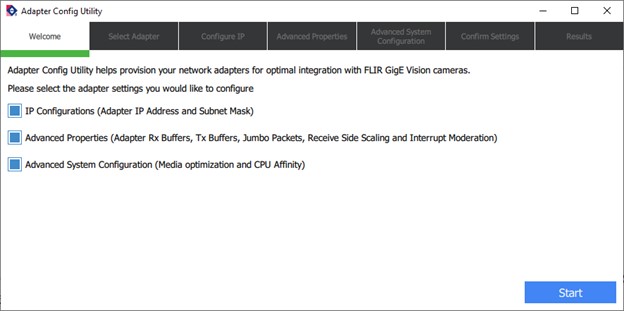
The Adapter Config Utility is installed with the Spinnaker SDK; it allows you to control the configuration of your network adapter. The default location for this .exe file is C:\Program Files\Teledyne\Spinnaker\bin64\vs2015 if you downloaded the Spinnaker 64x Windows and selected to use Visual Studio 2015 in the installation process.
The Adapter Config Utility lists your network adapters and allows you to access the following:
- Adapter IP address
- Subnet mask
- Default gateway
- Adapter receive buffers
- Transmit buffers
- Jumbo packets
- Interrupt moderation rate
- Receive side scaling
- Media optimization
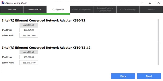
Setting the Adapter IP Address, Subnet Mask, and Default Gateway
You can either fill in the IP address manually or use “Auto Fill All” which assigns the IP address for the network adapter automatically. The camera and network adapter must be on the same subnet for the camera to show up in SpinView.
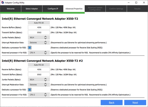
Setting the Adapter Advanced Properties
The receive buffer is the size of system memory that the adapter can use for receiving packets, which can be increased to help improve the performance of incoming network traffic.
On PCs with limited RAM (<4GB), setting the receive buffer size to the maximum may have a negative impact as buffers consume system memory. On most systems the maximum setting can be applied without reducing available memory.
The adapter uses the transmit buffer to send packets.
The jumbo packet size influences the number of interrupts generated which affects CPU usage. The larger the packet size, the fewer the interrupts for the same amount of data. To minimize CPU usage, increase the packet size.
The upper limit depends on your host adapter, your Ethernet switches (if used), and the camera. Usually, the limit is 9000 or 9014.
Select 9014 for Jumbo Packets. If your adapter does not support such a large packet (or MTU) size, then you will experience slightly higher CPU usage.
The interrupt moderation rate sets the rate at which the controller moderates or delays the generation of interrupts. Moderation helps optimize network throughput and CPU utilization.
At higher data rates, a high interrupt moderation setting may improve system performance.
Receive side scaling (RSS) is a network driver technology that enables the efficient distribution of network receive processing across multiple CPUs in multiprocessor systems. For optimal configurations, we recommend reserving a dedicated CPU for each camera. RSS should be used along with proper CPU affinity management. For more information, please see Using the Spinnaker Multi-core GigE Optimizer.
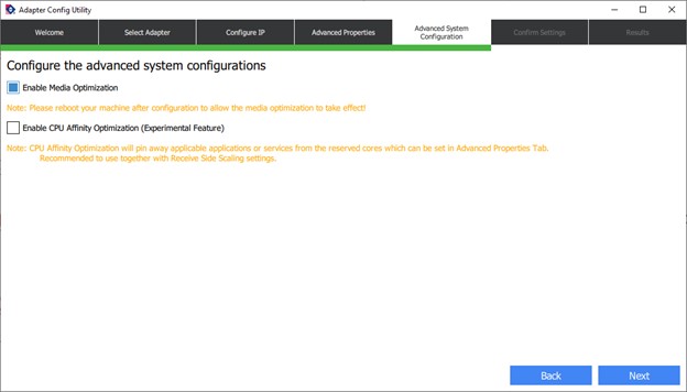
Setting Advanced System Configuration
Machine Vision PCs should be optimized to run image acquisition and post processing.
Media Optimization – allows time sensitive image acquisition to take priority over multi media tasks such as video streaming in Zoom or Teams meetings.
CPU Affinity Service – should always be used along with Receive Side Scaling (RSS). This optimization will bind all system process and services to a range of CPUs.
Configuring the Camera's IP Address
The camera's IP address can be assigned in three ways:
Persistent—Both the adapter and the camera have a fixed IP address that will not change. Generally the address is within a closed network range of 192.168.X.X. The adapter and the camera must be on the same subnet.
Note: Persistent IP addressing is recommended for multiple cameras on multiple ports.
Dynamic (DHCP)—Both the camera and the adapter are set to automatically obtain an IP address. This means that the IP address will dynamically change (within a range) every time the camera or computer is restarted. It may take up to one minute for the IP address to resolve and the camera to enumerate.
Note: In order to use DHCP, you need to have a DHCP server running; this article does not go over how to set this up.
Default (LLA)—Both the camera and the adapter use a default IP address from the link-local address block 169.254.x.x.
The cameras assign its current IP address in the following sequence:
- Persistent - Uses the defined IP address. If not available, then;
- DHCP – Attempts to find a dynamic IP address. If not available, then;
- LLA – Uses the default IP address
Use SpinView to set the camera's IP address.
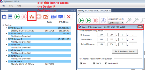
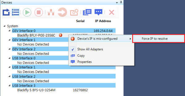
Auto Force IP
SpinView can automatically force an IP address refresh. This detects the IP address of the network adapter and automatically sets the camera’s IP address relative to the adapter. If a camera’s IP address is not properly set to match the host adapter the camera is attached to, a red circle with a white exclamation mark inside of it is shown beside the camera.
Allocating Bandwidth
The User Datagram Protocol (UDP) used by the GigE Vision standard provides no guaranteed transmission or fixed timing mechanism. Therefore, bandwidth must be managed by adjusting Device Link Throughput Limit based on desired resolution and frame rate.
Calculating Required Bandwidth
The maximum bandwidth for GigE interface is 125 MB. This includes image data, control data and image resends, which occur when frames are dropped. Each image and packet has a certain amount of overhead that uses some bandwidth; therefore, when calculating your bandwidth requirements, you should not attempt to use the full maximum of 125 MB.
To calculate your bandwidth requirements:
Determine your required resolution, frame rate and pixel format (bytes per pixel) as follows:
Height x Width x Frame Rate x Bytes per Pixel = Bandwidth in MB
As an example, for an image that is VGA, 82 FPS, in Mono8:
640 (H) x 480 (W) x 82 (FPS) x 1 (BPP) = ~ 25 MB
Understanding your required bandwidth helps you determine what kind of configuration you need for setting up multiple cameras.
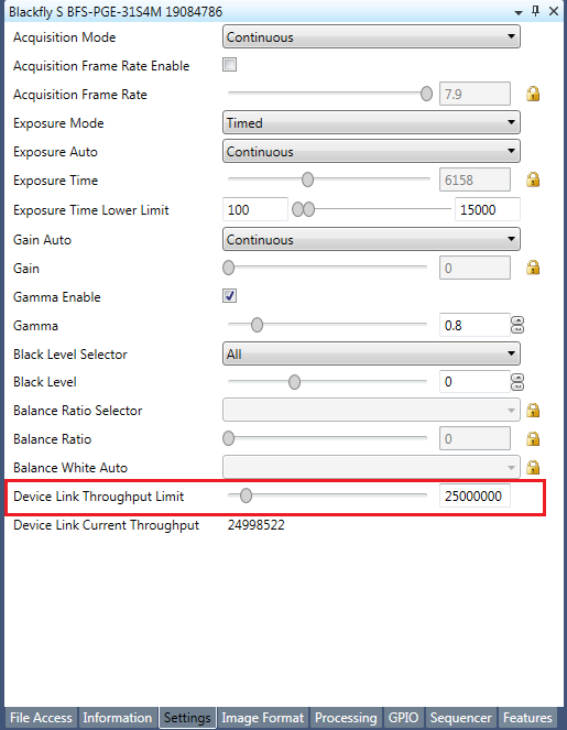
Once you have calculated your required bandwidth, you can allocate an amount to each camera by adjusting the Device Link Throughput Limit. Allocating a specific amount to each camera helps to avoid dropped packets due to a data burst. You would do this in a set up with multiple cameras, or in a situation where the system bandwidth might be limited or shared due to hardware architecture.
To allocate 25 MB ~ 20% of bandwidth:
Device Link Throughput Limit = 25000000
To allocate 55 MB ~ 45% of bandwidth:
Device Link Throughput Limit = 55000000
Troubleshooting
Solving Enumeration Problems
If your camera is not showing up in SpinView, consider the following:
Is the camera powered?
- Check that the camera LED is on
- Power is provided via GPIO on Flea3 GigE and Grasshopper2 GigE. Power is provided via PoE or GPIO on Blackfly S or Blackfly
Is there an IP conflict?
- Ensure the camera is using a unique IP address
- The camera and host adapter must be on the same subnet
Is the firewall blocking Spinnaker?
- Add Spinnaker to your firewall program’s exceptions list or disable the firewall
Is other network traffic blocking your camera?
- Use a dedicated adapter for the camera and a separate adapter for the Internet or other devices
Do you see a red exclamation mark next to your camera?
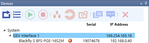
This is usually caused by unmatched subnet address between the camera and the network adapter.
- Auto-force IP and Refresh
or
- Manually change the IP address of the camera to match the subnet of the adapter